SKD Series Inverter SKD Kit
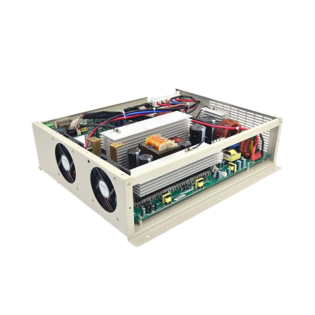
3kW-11kW hybrid solar inverter circuit board SKD
Small and space-efficient design that fits easily into tower-mounted, floor-standing, wall-mounted, and rack-mounted battery cabinets.
Easily powers inductive loads such as electric drills, water pumps, air conditioners, and washing machines.
Supports WiFi or remote data transmission. The mobile APP allows real-time monitoring of inverter and battery system parameters anytime, anywhere.
The SKD series belongs to the solar inverter skd kits range. Review the exact model in the specification table rather than selecting on the series name alone.
Small and space-efficient design that fits easily into tower-mounted, floor-standing, wall-mounted, and rack-mounted battery cabinets. Easily powers inductive loads such as electric drills, water pumps, air conditioners, and washing machines.
Structural Features
Key features of the SKD platform:
- Small and space-efficient design that fits easily into tower-mounted, floor-standing, wall-mounted, and rack-mounted battery cabinets.
- Easily powers inductive loads such as electric drills, water pumps, air conditioners, and washing machines.
- Supports WiFi or remote data transmission. The mobile APP allows real-time monitoring of inverter and battery system parameters anytime, anywhere.
- Automatically activates lithium batteries under low-voltage conditions, saving time and improving ease of use.
Product Advantages
Small and space-efficient design that fits easily into tower-mounted, floor-standing, wall-mounted, and rack-mounted battery cabinets.
Easily powers inductive loads such as electric drills, water pumps, air conditioners, and washing machines.
Supports WiFi or remote data transmission. The mobile APP allows real-time monitoring of inverter and battery system parameters anytime, anywhere.
Automatically activates lithium batteries under low-voltage conditions, saving time and improving ease of use.
Keep the SKD manual and model label with the system records. During service, follow its isolation procedure and inspect ventilation, connections and alarms according to the installation conditions. Do not apply maintenance instructions from another series.
For a SKD quotation, send the exact model, quantity, destination market, electrical requirements and expected operating duty. Identify any branding, packaging or documentation requirements separately so the supplied configuration is clear.
Technical Parameters
| Output Voltage: | |
|---|---|
| Rated Power : | |
| Availability: | |
|
| |
| Model | GP3024SMH | GP4024SMH | GP5548SMH | GP6248SMH | GP8648SMH | GP11048SMH |
| AC Input | ||||||
| Input Formation | L+N+PE | |||||
| AC Input | 220/230/240VAC | |||||
| Input Voltage Range | 90-280VAC±3V(Normal Mode) 170-280VAC±3V (UPS Mode) | |||||
| Frequency | 50/60Hz(Adaptive) | |||||
| Inverter Output | ||||||
| Rated Power | 3000W | 4000W | 5500W | 6200W | 8600W | 11000W |
| Dual Output Power | 3600W | 4500W | 6500W | 6500W | 11000W | 12000W |
| Output Voltage | 220/230/240VAC±5% | |||||
| Output Frequency | 50/60Hz±0.1% | |||||
| Output Wave | Pure Sine Wave | |||||
| Transfer Time(Adjustable) | 10ms for Computer Equipment,20ms for Household Equipment | |||||
| Peak Power | 6000VA | 8000VA | 11000VA | 12400VA | 17200VA | 22000VA |
| Overload Ability | Battery Mode: 21s@105%~150% Load; 11s@150%~200% Load; 400ms@>200% Load | |||||
| Grid connected Operation | ||||||
| Output Voltage | 220/230/240VAC | |||||
| Grid Voltage Range | 170-265VAC | |||||
| Grid Frequency Range | 49-51±1Hz/59-61±1Hz | |||||
| Output Current | 13A | 15.7A | 21.7A | 23.9A | 26.9A | 47.8A |
| Power Factor Range | >0.99 | |||||
| Max efficiency (DC/AC) | 0.98 | |||||
| Battery Charging | ||||||
| Rated Voltage | 24VDC | 24VDC | 48VDC | 48VDC | 48VDC | 48VDC |
| Constant Charging Voltage | 28.2VDC | 28.2VDC | 56.4VDC | 56.4VDC | 56.4VDC | 56.4VDC |
| Float Charging Voltage | 27VDC | 27VDC | 54VDC | 54VDC | 54VDC | 54VDC |
| PV Charging Method | MPPT | MPPT | MPPT | MPPT | 2*MPPT | 2*MPPT |
| PV Input & Charging | ||||||
| Max PV Input | 5000W | 6500W | 8500W | 8500W | 2*6500W | 2*7500W |
| MPPT Tracking Range | 60~500VDC | 90~500VDC | ||||
| MAX PV Input Voltage | 500VDC | |||||
| Maximum pulse PV input current | 27A | 36A | 36A | 36A | 36A/36A | 36A/36A |
| Maximum rated PV input current | 18A | 27A | 27A | 27A | 27A/27A | 27A/27A |
| MAX PV Charge Current | 100A | 120A | 100A | 120A | 150A | 150A |
| MAX AC Charge Current | 60A | 100A | 100A | 100A | 150A | 150A |
| MAX Charge Current | 100A | 120A | 100A | 120A | 150A | 150A |
| Communication & Display | ||||||
| LCD | Can display operating mode/load/input/output | |||||
| RS232 | Baud Rate 2400 | |||||
| Expansion Slot Communication Interface | Lithium Battery BMS Communication Card,WIFI 2×5PIN/Pitch2.54mm | |||||
| Parallel Interface | Not Support Parallel | Support Parallel | ||||
| Environmental | ||||||
| Operating Temperature | -10°C~50°C | |||||
| Storage Temperature | -15°C~60°C | |||||
| Ork Altitude | No more than 1000m, If 1000m<,Rate power will lower, MAX 4000m, Refer IEC62040 | |||||
| Operating Environment Humidity | Non Condensing | |||||
| Noise | ≤50dB | |||||
| Weight(KG) | 6.58 | 6.6 | 7.78 | 7.78 | 7.78 | 15.3 |
Use the SKD electrical limits as the starting point for system design. Confirm the AC supply where applicable, battery voltage, PV string limits and equipment connected to the output. Optional functions must be specified with the order.
Check the battery and charging requirements for the selected SKD model. Match permitted charge and discharge current, charging profile and any supported BMS protocol. A matching connector or nominal voltage alone does not confirm compatibility. For a battery-free or DC-only product, use only the interfaces listed in its model table.
For a SKD quotation, send the exact model, quantity, destination market, electrical requirements and expected operating duty. Identify any branding, packaging or documentation requirements separately so the supplied configuration is clear.
The table describes one published model revision. Confirm the current supply configuration before ordering.
Before You Order
Use the SKD electrical limits as the starting point for system design. Confirm the AC supply where applicable, battery voltage, PV string limits and equipment connected to the output. Optional functions must be specified with the order.
Electrical Match
Check the battery and charging requirements for the selected SKD model. Match permitted charge and discharge current, charging profile and any supported BMS protocol. A matching connector or nominal voltage alone does not confirm compatibility. For a battery-free or DC-only product, use only the interfaces listed in its model table.
Installation Plan
Install the SKD product within the temperature, ventilation and enclosure conditions stated in its manual. Specify cable sizes, isolation and protection through a qualified installation design. Product dimensions and clearances should be checked before cabinet or mounting work.
Supply Configuration
SKD Series — Selection and Application
The SKD series belongs to the solar inverter skd kits range. Review the exact model in the specification table rather than selecting on the series name alone.
Small and space-efficient design that fits easily into tower-mounted, floor-standing, wall-mounted, and rack-mounted battery cabinets. Easily powers inductive loads such as electric drills, water pumps, air conditioners, and washing machines.
Model selection
For SKD, first identify the required electrical interface and continuous load.
Capacity, charging limits and case dimensions vary by model. Check the chosen configuration against the matching data sheet.
Operating features
Small and space-efficient design that fits easily into tower-mounted, floor-standing, wall-mounted, and rack-mounted battery cabinets.
Easily powers inductive loads such as electric drills, water pumps, air conditioners, and washing machines.
Supports WiFi or remote data transmission. The mobile APP allows real-time monitoring of inverter and battery system parameters anytime, anywhere.
Automatically activates lithium batteries under low-voltage conditions, saving time and improving ease of use.
System integration
Use the SKD electrical limits as the starting point for system design. Confirm the AC supply where applicable, battery voltage, PV string limits and equipment connected to the output. Optional functions must be specified with the order.
Battery and charging
Check the battery and charging requirements for the selected SKD model. Match permitted charge and discharge current, charging profile and any supported BMS protocol. A matching connector or nominal voltage alone does not confirm compatibility. For a battery-free or DC-only product, use only the interfaces listed in its model table.
Installation planning
Install the SKD product within the temperature, ventilation and enclosure conditions stated in its manual. Specify cable sizes, isolation and protection through a qualified installation design. Product dimensions and clearances should be checked before cabinet or mounting work.
Monitoring and interfaces
Check which monitoring ports and communication options are included on the selected SKD model. Confirm accessory hardware, protocol and firmware before relying on remote monitoring, battery communication or expansion.
Frequently asked questions
Which SKD model should I choose? Start with the model table and the loads or battery system, then confirm the final configuration before ordering.
Are all optional functions included? No. Availability depends on the model, hardware and agreed supply specification.
Can I combine data from different catalogues? Use one matching model and revision. Confirm any differing values with the supplier.
Discuss your requirements
Contact Techfine Group with your SKD requirements. Include the model and the application so the electrical configuration and supporting documents can be checked.