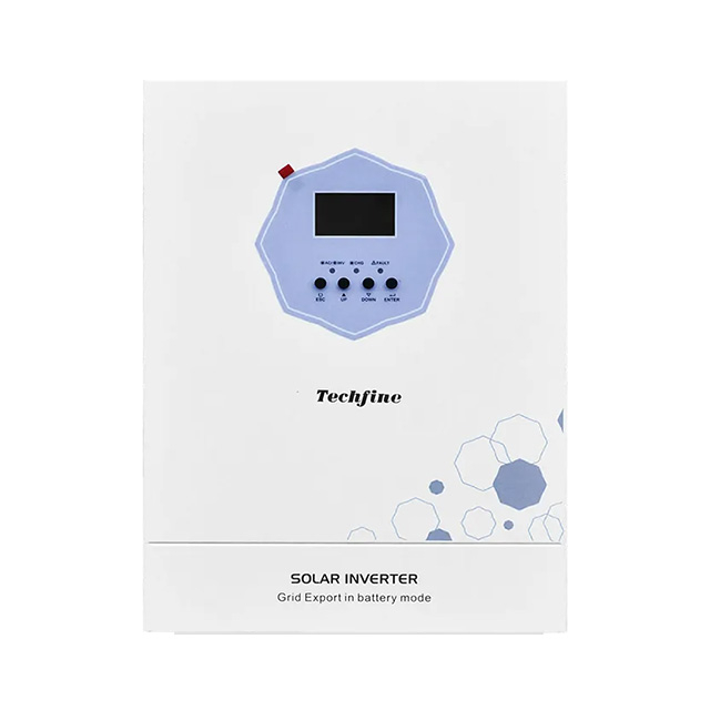
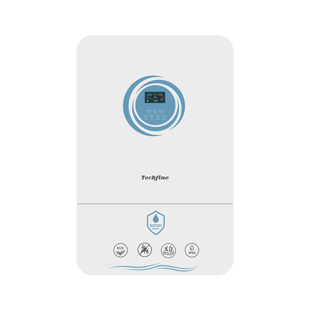
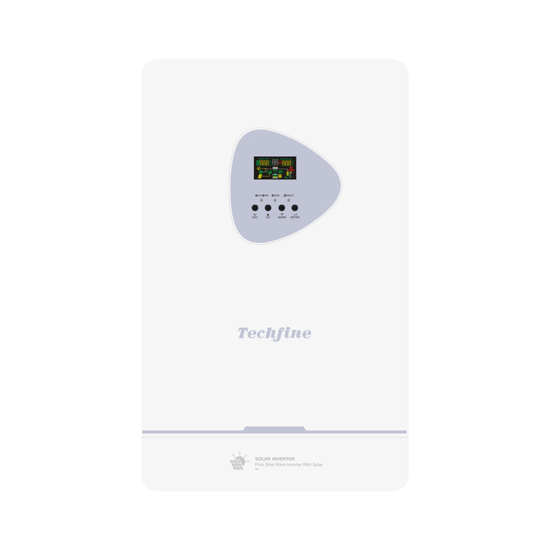
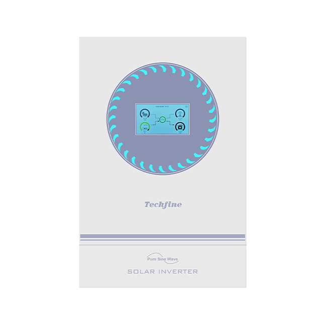
QA Series Hybrid Solar Inverter
QA Series Hybrid Solar Inverter 1.2-12 kW
Supports on-grid, off-grid, and hybrid modes. Enables battery-free operation and flexible adaptation to different scenarios. Battery power selling modes (SUF & PEC) support both energy storage and grid feed-in.
Adopts silicon carbide (SiC) devices for higher efficiency, lower thermal loss, and reduced self-consumption. Ensures stable long-term operation with minimal overheating, noise, and failure rates.
Optional WiFi module enables real-time power generation monitoring, fault diagnostics, and error alerts. High-performance DSP improves system responsiveness and overall control accuracy.
The QA series belongs to the hybrid solar inverters range. Review the exact model in the specification table rather than selecting on the series name alone.
Supports on-grid, off-grid, and hybrid modes. Enables battery-free operation and flexible adaptation to different scenarios. Battery power selling modes (SUF & PEC) support both energy storage and grid feed-in. Adopts silicon carbide (SiC) devices for higher efficiency, lower thermal loss, and reduced self-consumption. Ensures stable long-term operation with minimal overheating, noise, and failure rates.
Structural Features
Key features of the QA platform:
- Supports on-grid, off-grid, and hybrid modes. Enables battery-free operation and flexible adaptation to different scenarios. Battery power selling modes (SUF & PEC) support both energy storage and grid feed-in.
- Adopts silicon carbide (SiC) devices for higher efficiency, lower thermal loss, and reduced self-consumption. Ensures stable long-term operation with minimal overheating, noise, and failure rates.
- Optional WiFi module enables real-time power generation monitoring, fault diagnostics, and error alerts. High-performance DSP improves system responsiveness and overall control accuracy.
- Built-in CT anti-backflow function intelligently controls power flow, prioritizes self-use, prevents reverse current, and complies with energy regulations. Fast response time of 20 ms ensures precise control.
- Compatible with multiple lithium battery brands. Supports intelligent battery activation and automatic restart after over-discharge using both PV and utility power.
Product Advantages
Supports on-grid, off-grid, and hybrid modes. Enables battery-free operation and flexible adaptation to different scenarios. Battery power selling modes (SUF & PEC) support both energy storage and grid feed-in.
Adopts silicon carbide (SiC) devices for higher efficiency, lower thermal loss, and reduced self-consumption. Ensures stable long-term operation with minimal overheating, noise, and failure rates.
Optional WiFi module enables real-time power generation monitoring, fault diagnostics, and error alerts. High-performance DSP improves system responsiveness and overall control accuracy.
Built-in CT anti-backflow function intelligently controls power flow, prioritizes self-use, prevents reverse current, and complies with energy regulations. Fast response time of 20 ms ensures precise control.
Compatible with multiple lithium battery brands. Supports intelligent battery activation and automatic restart after over-discharge using both PV and utility power.
For a QA quotation, send the exact model, quantity, destination market, electrical requirements and expected operating duty. Identify any branding, packaging or documentation requirements separately so the supplied configuration is clear.
Technical Parameters
| Parameter | QA1212 | QA2012 | QA3624 | QA6248 | QA12048 |
|---|---|---|---|---|---|
| Input | |||||
| Input wiring | L+N+PE | ||||
| Rated input voltage | 208/220/230/240VAC | 220/230/240VAC | |||
| Input voltage range | 90-280 VAC ±3 V (normal mode); 170-264 VAC ±3 V (UPS mode) | 90-280 VAC ±3 V (normal mode); 170-280 VAC ±3 V (UPS mode) | |||
| Input frequency range | 50 / 60 Hz (auto-sensing) | ||||
| Output | |||||
| Rated power (battery mode) | 1200W | 1600W | 3600W | 6200W | 11000W |
| Rated power (PV mode) | — | 2000W | 3600W | 6200W | 12000W |
| Output voltage | 208/220/230/240VAC | 220/230/240VAC±5% | |||
| Output frequency | 50/60Hz±0.1% | ||||
| Waveform | Pure sine wave | ||||
| Transfer time (selectable) | 10 ms (computer loads) / 20 ms (home appliances) | ||||
| Peak power | 2400VA | 3200VA | 7200VA | 12400VA | 22000VA |
| Overload capability | Battery mode: 60 s @ 102-110% load; 10 s @ 120-200% load | Battery mode: 11 s @ 105-150% load; 2 s @ 150-200% load; 400 ms @ >200% load | |||
| Grid-tie operation | |||||
| Output voltage | Self-consumption only (no grid feed-in) | 220/230/240VAC | |||
| Grid feed-in voltage range | — | 100-280VAC | |||
| Grid feed-in frequency range | — | 47~53±1Hz/57~62±1Hz | |||
| Rated output current | — | 8.7A | 15.7A | 26.9A | 52.2A |
| Power factor range | — | >0.99 | |||
| Max. conversion efficiency (DC/AC) | — | 0.98 | |||
| Battery | |||||
| Rated voltage | 12Vdc | 24Vdc | 48Vdc | ||
| Constant charge voltage (adjustable) | 14.1Vdc | 28.2Vdc | 56.4Vdc | ||
| Float charge voltage (adjustable) | 13.5Vdc | 27Vdc | 54Vdc | ||
| Solar charger | |||||
| PV charging type | MPPT | Dual-channel MPPT | |||
| Max. PV input power | 800W | 3000W | 5000W | 8500W | 2×8500W |
| MPPT input voltage range | 17-115Vdc | 60-500Vdc | 90~500Vdc | ||
| Optimal Vmp range | 42~63Vdc | 300~400Vdc | 360~430Vdc | ||
| Max. PV input voltage | 115Vdc | 500Vdc | |||
| Max. PV input current (pulse) | — | 21A | 36A | 36A/36A | |
| Max. rated PV input current | 15A | 27A | 27A/27A | ||
| Max. PV charging current | 50A | 100A | 120A | 150A | |
| Max. utility charging current | 50A | 80A | 100A | 150A | |
| Max. total charging current | 100A | 120A | 150A | ||
| Display | |||||
| LCD display | Shows operating mode / load / input / output, etc. | ||||
| Communication | |||||
| RS232 | None | Baud rate 2400 | |||
| Expansion slot | None | Li-battery BMS card, Wi-Fi card, CT port | |||
| Parallel interface | Not available | Parallel / networking capable | |||
| Output connection | 1 universal socket + terminal block | Terminal block | |||
| Environment | |||||
| Operating temperature | -10 to 60 °C | -10 to 50 °C | |||
| Operating humidity | 5-95% (non-condensing) | 20-95% (non-condensing) | |||
| Storage temperature | -15 to 60 °C | ||||
| Altitude | <=1000 m without derating; derated above 1000 m, max. 4000 m (ref. IEC 62040) | ||||
| Noise level | ≤50 dB | ||||
| Physical | |||||
| Dimensions D×W×H (mm) | 300×217×91 | 355×294×118 | 440.3×309×125.5 | 514×360×161 | |
| Weight (ref., kg) | 3.4 | 5.5 | 6 | 8 | 19 |
| Standards & certification | |||||
| Standards & certification | EN-IEC 60335-1, EN-IEC 60335-2-29, IEC 62109-1 | ||||
Use the QA electrical limits as the starting point for system design. Confirm the AC supply where applicable, battery voltage, PV string limits and equipment connected to the output. Optional functions must be specified with the order.
Check the battery and charging requirements for the selected QA model. Match permitted charge and discharge current, charging profile and any supported BMS protocol. A matching connector or nominal voltage alone does not confirm compatibility. For a battery-free or DC-only product, use only the interfaces listed in its model table.
For a QA quotation, send the exact model, quantity, destination market, electrical requirements and expected operating duty. Identify any branding, packaging or documentation requirements separately so the supplied configuration is clear.
The table describes one published model revision. Confirm the current supply configuration before ordering.
Before You Order
Use the QA electrical limits as the starting point for system design. Confirm the AC supply where applicable, battery voltage, PV string limits and equipment connected to the output. Optional functions must be specified with the order.
Electrical Match
Check the battery and charging requirements for the selected QA model. Match permitted charge and discharge current, charging profile and any supported BMS protocol. A matching connector or nominal voltage alone does not confirm compatibility. For a battery-free or DC-only product, use only the interfaces listed in its model table.
Installation Plan
Install the QA product within the temperature, ventilation and enclosure conditions stated in its manual. Specify cable sizes, isolation and protection through a qualified installation design. Product dimensions and clearances should be checked before cabinet or mounting work.
Supply Configuration
QA Series — Selection and Application
The QA series belongs to the hybrid solar inverters range. Review the exact model in the specification table rather than selecting on the series name alone.
Supports on-grid, off-grid, and hybrid modes. Enables battery-free operation and flexible adaptation to different scenarios. Battery power selling modes (SUF & PEC) support both energy storage and grid feed-in. Adopts silicon carbide (SiC) devices for higher efficiency, lower thermal loss, and reduced self-consumption. Ensures stable long-term operation with minimal overheating, noise, and failure rates.
Model selection
For QA, first identify the required electrical interface and continuous load.
Parameter | QA1212 | QA2012 | QA3624 | QA6248 | QA12048 Input wiring | L+N+PE
Operating features
Supports on-grid, off-grid, and hybrid modes. Enables battery-free operation and flexible adaptation to different scenarios. Battery power selling modes (SUF & PEC) support both energy storage and grid feed-in.
Adopts silicon carbide (SiC) devices for higher efficiency, lower thermal loss, and reduced self-consumption. Ensures stable long-term operation with minimal overheating, noise, and failure rates.
Optional WiFi module enables real-time power generation monitoring, fault diagnostics, and error alerts. High-performance DSP improves system responsiveness and overall control accuracy.
Built-in CT anti-backflow function intelligently controls power flow, prioritizes self-use, prevents reverse current, and complies with energy regulations. Fast response time of 20 ms ensures precise control.
Compatible with multiple lithium battery brands. Supports intelligent battery activation and automatic restart after over-discharge using both PV and utility power.
System integration
Use the QA electrical limits as the starting point for system design. Confirm the AC supply where applicable, battery voltage, PV string limits and equipment connected to the output. Optional functions must be specified with the order.
Battery and charging
Check the battery and charging requirements for the selected QA model. Match permitted charge and discharge current, charging profile and any supported BMS protocol. A matching connector or nominal voltage alone does not confirm compatibility. For a battery-free or DC-only product, use only the interfaces listed in its model table.
Installation planning
Install the QA product within the temperature, ventilation and enclosure conditions stated in its manual. Specify cable sizes, isolation and protection through a qualified installation design. Product dimensions and clearances should be checked before cabinet or mounting work.
Monitoring and interfaces
Check which monitoring ports and communication options are included on the selected QA model. Confirm accessory hardware, protocol and firmware before relying on remote monitoring, battery communication or expansion.
Frequently asked questions
Which QA model should I choose? Start with the model table and the loads or battery system, then confirm the final configuration before ordering.
Are all optional functions included? No. Availability depends on the model, hardware and agreed supply specification.
Can I combine data from different catalogues? Use one matching model and revision. Confirm any differing values with the supplier.
Discuss your requirements
Contact Techfine Group with your QA requirements. Include the model and the application so the electrical configuration and supporting documents can be checked.