A dual MPPT inverter gives a designer two independently controlled PV operating points. That can be useful when roof areas face different directions or experience different conditions, but it does not remove the need for string design. The right starting point is a roof and module schedule, followed by checks against the exact inverter input limits. Counting connectors or relying on a series headline is not enough.
Map the roof before choosing the tracker arrangement
Divide the available space into areas with consistent orientation and tilt. Record obstacles, possible seasonal shadows, usable dimensions and maintenance access. An east-facing section and a west-facing section may produce differently through the day even when their installed module capacities are equal. Treating the entire roof as one uniform rectangle conceals the conditions that make independent tracking useful.
Use a drawing that identifies each proposed module group and the route to the inverter. Add the module model and count for each area rather than just its total kilowatts. A roof with several small sections can be harder to match to an inverter than a large uniform roof, because each electrical string must still satisfy the operating requirements of the input that receives it.
Distinguish trackers, strings and connectors
An MPPT channel controls an operating point. A string is a series-connected group of PV modules. A connector is a physical connection. Several physical inputs can belong to one tracker; their presence alone does not prove independent control. Request the input grouping diagram and the limits for each tracker, each string connection and the inverter as a whole.
Likewise, two MPPT channels do not mean two AC outputs or two separately usable AC power supplies. These are different sides of the inverter. Keeping the terminology separate helps a buyer avoid requesting load-priority functionality when the actual need is to manage different PV arrays, or selecting a second tracker in the mistaken belief that it will increase the AC output rating.
When independent tracking is useful
Separating PV groups can make sense when their electrical operating conditions differ. Different orientations, tilt angles or shading patterns are reasons to evaluate separate channels. However, independent tracking cannot restore sunlight that an obstruction blocks. Nor does it make arbitrary module combinations acceptable. The designer still needs to assess the module characteristics and the approved configuration.
There is also an important exception to simplistic advice about orientation. SMA discusses manufacturer-approved polystring configurations that place differently oriented strings on one tracker. Its discussion emphasizes design assessment rather than a universal rule. That example is not blanket approval for a Techfine input arrangement: apply only configurations supported by the selected inverter’s documentation. The relevant question is whether the proposed electrical layout is permitted and performs acceptably.
Use a tracker allocation worksheet
| Design item | Tracker A | Tracker B |
|---|---|---|
| Roof area and orientation | Identify the first physical group | Identify the second physical group |
| Module model and string length | Record exact module and count | Record exact module and count |
| Parallel strings | Check permitted grouping and current | Check permitted grouping and current |
| Voltage across expected temperatures | Check maximum and operating conditions | Check maximum and operating conditions |
| Shading and access constraints | Document obstacles and service space | Document obstacles and service space |
Fill the worksheet with calculated values and source documents before accepting a quotation. It gives the installer and supplier a common reference. If the proposed inverter changes, repeat the electrical comparison; an equal AC power rating does not establish equal PV input capability. A replacement module can also change the permissible arrangement even when its advertised wattage looks similar.
Check the voltage window at both temperature extremes
Maximum PV input voltage, startup voltage and the MPPT operating range describe different constraints. A string that remains below the maximum voltage may still fail to provide a suitable operating voltage in hot conditions. Conversely, a string that looks acceptable using nominal module values can exceed a limit when its open-circuit voltage rises in cold weather. Use the module’s documented coefficients and the project’s design temperatures.
Consider a purely illustrative string of ten modules, each with a stated open-circuit voltage of 40 V under a specified reference condition. Multiplication gives 400 V at that reference condition. It does not establish a safe string length for a 400 V or 500 V input, because the temperature correction and other design allowances have not been applied. The purpose of the example is to show why arithmetic at one condition is only a starting point.
Keep current limits separate from charging current
Check the permitted PV operating current and short-circuit current for each channel and connection. Adding strings in parallel changes the current requirement. A battery charging current printed elsewhere in the specification is not interchangeable with the PV input current limit. Those values refer to different circuit conditions and may be expressed at very different voltages.
Do not split the total advertised PV power equally between trackers unless the manual actually permits that arrangement. Channels can have individual limits in addition to a combined limit. Confirm whether both must be populated, whether unequal array sizes are supported, and which combinations the supplier approves. These questions are especially useful for roofs where one side has much less available space.
Compare energy timing with site demand
Two orientations may spread production across a longer part of the day, but the practical benefit depends on the site. An office with morning demand and an evening workshop shift has a different consumption pattern from an empty daytime residence. Compare an hourly load profile with an appropriately modeled solar profile rather than assuming all generated energy will be used as it appears.
Ask the designer to identify the weather assumptions, shading model, conversion losses and any output limitation used in the estimate. Distinguish an expected yield from a guarantee. If storage is included, show the effect of charging limits and reserve policy separately. Tracker count alone cannot answer how much energy the customer will buy from the grid or how long the battery will support an outage.
Check the exact Techfine model column
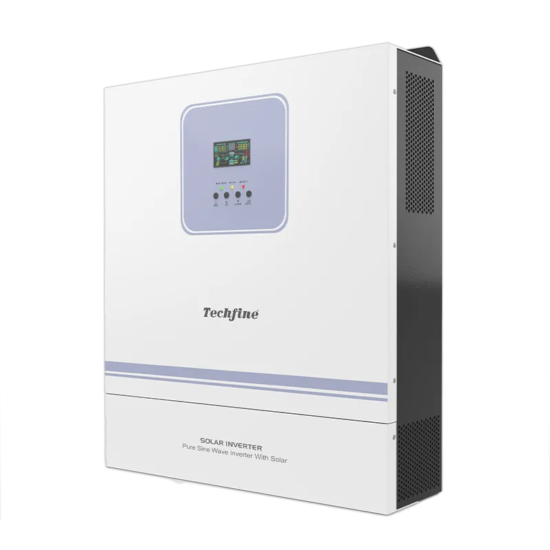
The Techfine GA Pro Plus specification illustrates why series-level wording needs a closer look: the table distinguishes MPPT arrangements across its model columns. Do not assume every power version has the same number of trackers because the series heading mentions two. Confirm the selected model code and current documentation with the supplier before placing an order.
The GA Pro Plus product page is a useful place to begin the product discussion. Send the roof drawing, module datasheet, proposed string allocation and project temperatures with the enquiry. Ask for written confirmation of the input arrangement, not just confirmation that the inverter’s total kilowatt rating matches the array headline.
Design handover and later expansion
Keep the final string schedule, tracker assignment, calculation revision and commissioning record together. Label the physical groups consistently with the monitoring names where the equipment supports that distinction. This helps a technician understand whether a difference between channels is expected from orientation or might warrant investigation. A lower afternoon reading from an east-facing group is not automatically evidence of a fault.
Reserve roof space does not necessarily mean the inverter can accept more modules later. Expansion can change voltage, current, string compatibility and permitted total power. Recheck the design before adding modules, and use qualified personnel for installation and testing. The original worksheet should make that review easier rather than becoming an informal permission to connect another string.
Frequently asked questions
Does each tracker need the same array size?
That depends on the inverter’s supported arrangements and input limits. Evaluate each channel and the combined system; do not impose equal sizes or assume unlimited asymmetry without documentation.
Can dual MPPT solve all shading problems?
No. It gives separate control of assigned groups, while actual irradiance and module behavior still determine available energy. Assess the shading source, duration and layout before choosing the electrical approach.
Which references help with the roof model?
SMA’s module layout guidance addresses roof surfaces, orientation and shading. Its polystring discussion explains why orientation decisions need design analysis. These are general planning references; Techfine model approval must come from the matching Techfine documentation.