A PV string that appears comfortably below an inverter’s voltage limit on a module label can exceed that limit in cold conditions. Open-circuit voltage changes with temperature, so string length must be checked against the site’s design conditions before equipment is connected. This is a design review, not a live measurement exercise. Use the exact module and inverter documentation and have a qualified designer approve the arrangement.
Identify the voltage that controls the upper-limit check
Open-circuit voltage, usually written Voc, describes a module voltage when it is not delivering current to a load under the stated conditions. It differs from the maximum-power operating voltage, Vmp. For the cold-voltage assessment, substituting Vmp for Voc can understate the voltage the equipment may encounter. Keep the two datasheet fields separate throughout the calculation.
The inverter’s absolute maximum PV input voltage also differs from its MPPT operating window. A high upper tracking value does not replace an absolute limit, and an array is not acceptable merely because it sometimes operates within the tracking window. Every applicable limit in the PV circuit must be respected under the required design conditions.
Collect the exact module data
Record the complete module model, its Voc reference value, the relevant temperature coefficient and the manufacturer’s calculation instructions. Check the coefficient’s units carefully. A value in percent per degree Celsius must be converted appropriately when used as a decimal multiplier. A coefficient expressed in volts per degree requires a different arithmetic form.
Use the correct datasheet revision for the delivered module. An apparently similar replacement can have a different electrical design. Do not choose whichever coefficient produces the most convenient result, and do not substitute the temperature coefficient of maximum power for the coefficient of Voc. Keep source documents with the string calculation so another reviewer can reproduce it.
Select the project’s design temperature deliberately
The relevant cold condition is not the average winter daytime temperature or the temperature on the day of installation. The designer must use the environmental assumptions required for the location and applicable design method. Specify the source and basis of the selected minimum temperature. Record it rather than leaving an unexplained number in a spreadsheet.
Canadian Solar’s module installation manual discusses cold-temperature correction of open-circuit voltage. That document is a manufacturer reference for its covered modules, not a universal substitute for another module’s instructions. Follow the actual module’s approved method and any requirements applicable to the project.
Work through an illustrative calculation
Assume an example module has Voc of 40 V at a 25°C reference condition and a Voc temperature coefficient of −0.25% per °C. Assume a design temperature of −10°C for this arithmetic example. The temperature change is −35°C. Multiplying −0.0025 per °C by −35°C gives +0.0875, corresponding to an 8.75% increase relative to the reference voltage.
The illustrative corrected module Voc is therefore 40 × 1.0875 = 43.5 V. Ten such modules in series would produce a calculated string value of 435 V using these assumptions. Twelve would give 522 V. None of these example numbers is a Techfine model specification, a recommended string length or a complete project design.
| Illustrative quantity | Value | Review point |
|---|---|---|
| Reference module Voc | 40 V | Use the actual module datasheet |
| Voc coefficient | −0.25%/°C | Convert percent to decimal correctly |
| Temperature difference | −35°C | Use the approved project temperature |
| Corrected example module Voc | 43.5 V | Apply all required manufacturer allowances |
| Ten-module example string | 435 V | Compare with every applicable circuit limit |
The sign is worth checking: with a negative Voc coefficient and a temperature below the reference, the calculated voltage increases. If a spreadsheet reports a decrease for this example, inspect the formula and units before using its output. An independent review is more valuable than assuming a familiar-looking result is correct.
Do not design directly against a convenient boundary
A calculation must include the allowances and tolerances required by the equipment instructions and applicable method. A result just below an inverter headline maximum is not automatically adequate evidence. Module tolerances, design assumptions and the complete circuit requirements need review. Ask the designer to explain the adopted method rather than adding an arbitrary margin without a basis.
Check associated components as well. Modules, disconnects, connectors, protection and other PV equipment have their own ratings and installation requirements. The inverter’s maximum cannot authorize a higher voltage for another component. Keep a list of the limiting ratings in the design record so a later substitution does not silently invalidate the arrangement.
Keep the lower operating check separate
Reducing string length to address cold Voc can create a different issue at the lower end of operation. The array must still meet the selected inverter’s startup and tracking requirements under relevant conditions. That second review uses its own data and reasoning. Passing the cold-voltage check is necessary but does not establish a complete workable string design.
This distinction prevents a common procurement shortcut: selecting the fewest modules that appear safe at the upper limit and assuming the rest will work automatically. The approved layout must satisfy upper voltage, operating voltage, input current and other model-specific constraints together. Document the results separately so failures are not hidden inside a single “compatible” checkbox.
Request the matching inverter specification
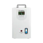
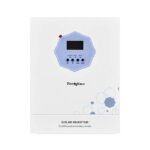
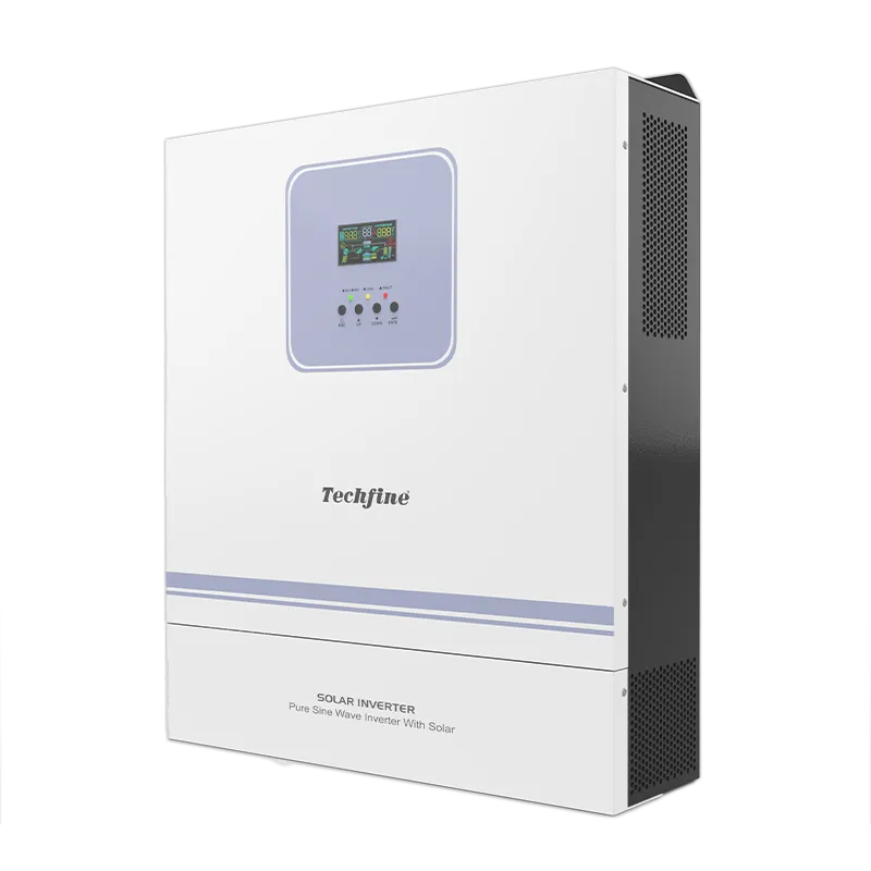
The Techfine GA Pro Plus page can begin the inverter selection discussion, while the manufacturer download center provides access to model documents. Confirm the exact version, absolute PV maximum and applicable input arrangement. Do not use the limits of a different power variant simply because the product family name matches.
Send the module datasheet, proposed series count, parallel-string arrangement and design-temperature basis with the enquiry. Ask for the string schedule to be reviewed against the exact quotation. A request containing only total array kilowatts leaves the supplier without the information needed to assess cold open-circuit voltage.
Preserve a calculation that can be audited
The final worksheet should identify its author, date, module revision, inverter model, temperature source, coefficient units and arithmetic. Include the applicable ratings and the resulting approved string count. Keep unresolved assumptions visible until they are confirmed. A screenshot of a calculator result without its inputs is difficult to maintain or verify.
Repeat the review when adding modules, replacing the module type or changing the inverter. Additional modules in series increase string voltage; an extension that looks physically convenient may be electrically unacceptable. Installation and testing should remain with qualified personnel following the approved design.
Frequently asked questions
Can I use array watts to check maximum voltage?
No. Total power does not define series string voltage. You need module Voc, temperature behavior, series count and the relevant equipment limits.
Is a warm-weather voltage measurement enough?
No. A measurement reflects its current conditions. The design must account for the required cold condition using the approved method.
Does adding parallel strings raise Voc in the same way?
Series and parallel arrangements affect different electrical quantities. Parallel grouping introduces current checks and compatibility requirements; it does not remove the need to assess each string’s voltage.