A solar array can show voltage while an inverter or charge controller remains idle. That observation alone does not prove a fault. Startup conditions, the MPPT operating range, available sunlight and charging permissions are different parts of operation. To investigate delayed morning startup, collect the model’s actual thresholds and a short operating log before changing the array or settings.
Distinguish startup from continued operation
Startup is the transition from an inactive state into operation. Continued tracking describes behavior after that transition. Equipment can use different thresholds for these states, sometimes with delays or other conditions. A range labelled MPPT does not necessarily tell you the exact voltage at which the equipment will first start on a particular morning.
The Victron SmartSolar 75/10 through 100/20 operation manual gives a useful model-specific example: startup requires PV voltage above the battery by a different amount from the voltage needed to continue charging. Those numbers apply to that equipment. Do not copy them into a Techfine inverter specification or treat them as a universal MPPT rule.
Read four different specification fields
| Field | Question it answers | What it does not establish alone |
|---|---|---|
| Maximum PV voltage | What upper input limit must not be exceeded? | Whether the array can start in weak light |
| Startup voltage or condition | What must be reached to begin operation? | The full range for continued tracking |
| MPPT operating range | Where can the tracker operate under the specified conditions? | That useful power exists at every moment |
| Charging enable conditions | Is charging permitted by the system controls? | That the PV array itself has a problem |
Some specifications also distinguish full-power voltage ranges or conditions that depend on battery state. Preserve the document’s labels rather than shortening every field to “PV voltage.” If a sales sheet and manual appear inconsistent, ask the supplier to resolve the exact model and revision before using the figures in a design.
Voltage does not equal available charging power
At dawn, the array’s measured or reported voltage can be present while available current and power remain small. An open-circuit or lightly loaded voltage reading is not a guarantee of useful energy delivery. Once the equipment tries to operate, the electrical conditions can change. That is why a single screenshot of PV volts and zero charge current is insufficient to identify the cause.
Log the time, weather, shading, reported PV voltage, PV power, battery state and device status together. A pattern across several comparable mornings is more informative than one reading. Distinguish normal low-light behavior from an alarm, disabled charging or an unexpected change after maintenance. The objective is to provide evidence for diagnosis, not to guess which setting to increase.
Check whether the battery wants to charge
A controller may limit or stop charging because the battery is full or because the charging stage calls for little current. A managed battery may also impose a charging restriction. An apparent lack of solar charging therefore does not always mean the PV input failed to start. Review the reported charge state and any battery or system messages before focusing exclusively on string length.
Ask whether the display shows solar generation, battery charging or net battery current. These are different quantities. If solar power is supplying loads, the battery’s net current may be small even while the array is working. Read the monitoring definitions so a normal power flow is not mistaken for a failed solar input.
Review the design without changing it experimentally
If the installed string arrangement is too close to a lower operating requirement, the designer should review it against module characteristics and expected conditions. Use the exact inverter input specifications and approved string schedule. Do not simply add another module because a morning reading seems low: increasing series count also changes cold open-circuit voltage and other constraints.
Keep the upper-limit assessment independent. A proposed change intended to improve startup must still respect absolute voltage, operating current, module compatibility and the manufacturer’s supported arrangements. Qualified personnel should approve any modification. This article does not instruct users to disconnect live PV wiring or probe exposed terminals.
Separate shading from equipment configuration
A roof area may receive direct sun later than expected because of a chimney, nearby building or seasonal solar position. Compare the physical exposure with the time in the log. If the inverter has more than one tracker, determine which array group belongs to each reported channel. A shaded east-facing input and an unshaded input need not begin useful production simultaneously.
Configuration can also affect the observation. Time-based charging policies, external control or an inactive input may need review, depending on the model. Record the current settings and ask the supplier which are relevant. Do not reset the whole system or override battery protections merely because another installation starts earlier.
Use a short diagnostic record
| Observation | Record alongside it | Next review |
|---|---|---|
| PV voltage present, little power | Sunlight, shade, device state and battery demand | Whether low-light behavior explains the result |
| Repeated start/stop indication | Time sequence and reported input values | Model thresholds and design operating conditions |
| Charging disabled message | Battery/BMS status and control permissions | Approved control configuration |
| New behavior after maintenance | What changed and which model documents apply | Qualified inspection of the changed arrangement |
The record should include firmware or software identification if the manufacturer requests it, but avoid changing firmware as a first diagnostic experiment. Provide the information through the supplier’s normal support channel. A clear sequence of observations helps distinguish an environmental pattern from a configuration problem or a fault requiring service.
Confirm Techfine thresholds for the exact version
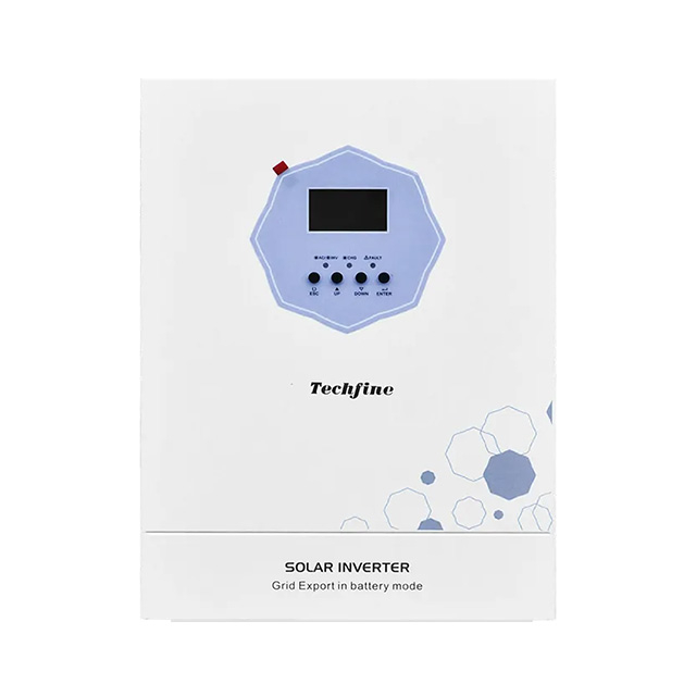
Begin the product discussion with the Techfine QA series page and obtain the matching manual from the Techfine download center or supplier. Ask explicitly which value is the startup condition, which is the MPPT range, and whether any full-power or battery-dependent condition applies. Do not substitute the range from another series.
Send the existing string schedule, module datasheet and operating log with the question. Identify whether the concern is late startup, repeated restarting, no battery charging or low energy yield. Those symptoms can overlap in a screenshot but require different checks. Precise wording improves the chance of a useful response without unnecessary equipment changes.
Frequently asked questions
Should solar charging start immediately when the display shows PV volts?
Not necessarily. The equipment must meet its startup conditions and have sufficient available input and permission to charge. Voltage alone does not confirm all of those conditions.
Can I lower a setting to make sunrise startup earlier?
Only use adjustments explicitly supported for the exact model and approved application. First establish whether the observed behavior is abnormal and what condition is preventing operation.
Does a later start prove a bad inverter?
No. Compare sunlight, array design, battery demand, settings and status messages. A diagnosis needs more than the clock time at which charging first appears.