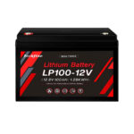
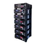
A battery advertised as approximately 5 kWh does not automatically support a 5 kW AC inverter at full output. Stored energy and permitted discharge current answer different questions. To assess the pairing, calculate the battery-side demand under relevant operating conditions and compare it with the exact pack’s continuous and transient limits. Include the inverter’s losses and the battery’s changing voltage rather than matching two similar numbers on product labels.
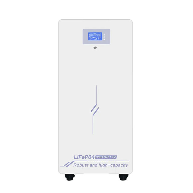
Identify the limits that actually control discharge
Collect the pack’s nominal voltage, permitted operating range, continuous discharge limit and any documented short-duration capability. Find the conditions attached to those ratings. Also identify protection thresholds, which are not necessarily intended operating targets. A BMS trip point should not be used as the normal discharge specification.
The Techfine LC specification lists continuous current, power and protection information in separate fields. Read the exact model column and resolve any ambiguity with the supplier. Do not combine a current value from a larger variant with the energy rating of a smaller one.
Calculate demand on the battery side
For an illustrative 5,000 W AC load and an assumed conversion efficiency of 90%, required input power is approximately 5,556 W. At an assumed battery voltage of 48 V, that corresponds to about 116 A before any additional demand outside the simplified calculation. The efficiency and voltage are examples, not a Techfine performance declaration.
If a hypothetical pack were limited to 100 A continuous discharge under the reviewed conditions, that example would exceed its continuous current allowance. An inverter capable of producing 5 kW would not remove the battery constraint. The equipment must be selected as a complete source-and-load system.
Review more than the nominal voltage point
At the same input power, lower DC voltage requires more current. A calculation using nominal voltage alone can therefore understate demand near the lower part of the approved operating range. Use the designer’s required conditions and the equipment documentation to assess the relevant maximum demand.
| Illustrative AC demand | Assumed efficiency | Assumed DC voltage | Approximate DC current |
|---|---|---|---|
| 5,000 W | 90% | 51.2 V | 109 A |
| 5,000 W | 90% | 48 V | 116 A |
| 5,000 W | 90% | 44 V | 126 A |
The table is a sensitivity example, not approval to operate a particular battery at any listed voltage. It demonstrates why the complete operating window and source limits matter. The final calculation must use suitable equipment data and design assumptions.
Separate continuous capability from a short event
A motor start or another transient can demand more than normal running operation. Compare the required magnitude and duration with the pack and BMS specifications, as well as the inverter’s own capability. A continuous-current rating is not the full answer to a transient requirement.
Conversely, a brief permitted peak does not authorize sustained operation at that current. Keep each rating labelled with its duration and conditions. If the documentation is incomplete, request clarification instead of assuming that a protective limit describes a usable overload allowance.
Account for the whole DC load
A battery can serve more than one device. Include other inverters or approved DC loads that may operate simultaneously. The main inverter’s screen may not describe every current leaving the battery bank. Use the complete system diagram and load schedule in the review.
Do not offset a required battery discharge rating with an optimistic assumption about solar production. Available PV contribution changes with weather and time. If a service must be supported when solar is unavailable, the battery requirement should reflect that condition explicitly.
Review temperature and battery-state conditions
A current rating can have temperature or other operating qualifications. Ask how the allowed discharge capability changes under the site’s expected conditions and how a managed battery communicates any restriction. A pack being warm, cold or nearly discharged can affect the actual operating situation.
Keep the intended service requirement separate from emergency protection. If the system repeatedly reaches a limit and disconnects, the fact that protection worked does not establish an acceptable backup design. Investigate the mismatch rather than treating repeated trips as normal operation.
Check installation capability through qualified design
The battery’s permitted current does not select the DC wiring and protection by itself. The approved installation must also accommodate the relevant voltage, current, fault conditions and equipment requirements. Connections, distribution and isolation belong in the qualified electrical design.
This guide does not provide cable sizes, fuse values or instructions for working on battery terminals. Do not bypass a BMS or protective device to reach the inverter’s advertised power. A properly selected system operates within its approved source and installation limits.
Compare possible remedies against the actual requirement
If one pack is inadequate, options may include a different approved pack, a supported multi-module arrangement or a revised load policy. Each needs a complete review. Adding storage energy does not guarantee a proportional change in permitted power unless the supported configuration establishes it.
Likewise, selecting a lower inverter rating is not the only possible response. The relevant question is how the actual load will be supplied reliably. Have the supplier explain the proposed source capability and the accepted operating limits in the quotation.
Use a source-capability worksheet
| Requirement | Evidence to obtain |
|---|---|
| Maximum sustained demand | AC load schedule and calculated DC demand |
| Starting event | Load profile and permitted battery/inverter transient behavior |
| Operating range | Voltage and temperature conditions used for the assessment |
| Battery capability | Exact model continuous and short-duration ratings |
| Complete installation | Approved distribution, protection and integration design |
Keep the worksheet with the equipment records. Recheck it when replacing the battery, changing the inverter or adding a significant load. A previous successful pairing does not automatically approve a different model with a similar kWh label.
Prepare a precise Techfine request
Use the LC battery page and the intended inverter model to identify the proposal. Provide continuous and starting loads, runtime objective, expected conditions and the required operating mode. Ask for confirmation of both energy and discharge-power capability.
Frequently asked questions
Does 5 kWh guarantee 5 kW for an hour?
No. Permitted power, usable energy and losses must all support that duty.
Can I use the protection trip current as the continuous rating?
No. Operating ratings and protective thresholds serve different purposes.
Will the inverter limit itself to the battery automatically?
Only rely on a documented supported control arrangement. Confirm the exact integration and settings.