A protection list on an MPPT controller datasheet describes functions inside the product, but it does not replace a correctly designed installation. Reverse-polarity, overvoltage and temperature protection each address particular conditions within stated limits. Buyers should ask what each function covers, how it responds and what recovery requires. This turns a broad feature list into useful acceptance and service information.
Map every protection to an electrical boundary
A controller has several different boundaries: the PV input, battery connection, possible DC load output and internal power-conversion components. A protection associated with one boundary should not be assumed to cover all the others. For example, a load-output current limit does not establish the allowable current of an inverter connected elsewhere on the battery system.
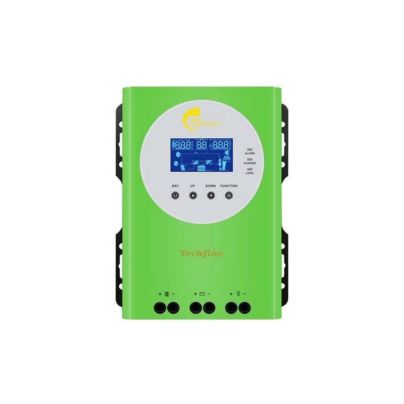
The Techfine M controller specification lists several input, battery, thermal and load functions. The detailed behavior must still be checked against the supplied model manual. Family-level wording is useful for initial screening, while the exact electrical limits determine whether the proposed arrangement is acceptable.
Reverse-polarity protection has defined scope
PV reverse-polarity protection and battery reverse-polarity protection concern different connections. Neither label should be interpreted as permission to deliberately reverse wiring during an acceptance test. An incorrect connection can expose equipment to conditions outside the protection’s design, particularly where other sources or substantial fault energy are present.
Ask the supplier which terminals are covered, whether there are restrictions and how an accidental event is indicated. The installer should verify polarity using the approved commissioning procedure before energization. Documentation of a correct connection is appropriate acceptance evidence; intentionally creating a wiring fault is not necessary to confirm a listed feature.
Input overvoltage protection does not raise the PV limit
The absolute PV voltage limit remains a design constraint even when overvoltage protection is advertised. A controller may stop conversion when a threshold is reached, yet its input components can still be exposed to array voltage. A protective shutdown should never be used as the design method for an array that exceeds the permitted input rating.
Use the approved string design, including cold-condition open-circuit voltage, to establish compliance before connection. If a supplier describes several voltage options within one family, select the correct model column. A higher-voltage sibling does not grant the same input tolerance to a lower-voltage unit in an identical-looking case.
Power limiting and current limiting are different checks
Charging-current limiting regulates a particular output quantity. Input power limiting concerns how much PV power the controller accepts under its supported operating conditions. Neither feature removes independent restrictions on PV voltage, array current, maximum permitted array size or terminal ratings.
When a proposed array can produce more than the controller’s nominal conversion power, obtain the model-specific oversizing rules. A vague claim that the controller will “only take what it needs” leaves important limits unresolved. The design needs an explicit permitted arrangement and the expected clipping behavior, not a general assumption based on one protective feature.
Battery protection and BMS control must be distinguished
A controller’s battery overcharge or under-voltage function does not automatically provide the same coverage as the battery’s own management system. The battery may impose temperature, cell-voltage or current conditions that the controller cannot determine from terminal voltage alone. Communication compatibility and charging permission therefore need separate review.
Likewise, a controller’s DC load disconnect may protect only loads attached to the designated output. It may have no authority over an inverter connected directly to the battery bus. Trace the actual control path before claiming that a feature protects every load in the installation.
Build a protection-and-recovery matrix
| Listed function | Clarification to request | Suitable verification evidence |
|---|---|---|
| PV reverse polarity | Covered terminals and operating restrictions | Manual reference and correct-polarity commissioning record |
| Input overvoltage | Design maximum, response and recovery | Approved array calculation and normal input record |
| Over-temperature | Reduction, shutdown and restart behavior | Thermal specification and representative operating log |
| Load over-current | Output boundary, rating and reset method | Compatible load schedule and alarm documentation |
| Battery-related limit | Local threshold versus external battery permission | Saved profile and supported battery-control arrangement |
Understand recovery before an alarm occurs
Some conditions clear automatically when normal operation returns; others require an approved intervention. Ask whether the controller retries, remains latched off or records a persistent alarm. Recovery behavior matters for an unattended site because repeated interruption can leave the battery undercharged even when no permanent hardware damage occurs.
Record what the operator should observe and which information to send to support. Include the exact alarm code, timestamp, displayed input and battery conditions, and any recent system change. Avoid repeated resets that erase useful context or conceal a recurring installation problem.
What belongs in installation protection
The qualified system designer still determines isolation, overcurrent protection, conductor selection, earthing and other installation requirements under applicable rules and equipment instructions. Internal electronic functions do not automatically replace these measures. Keep product protection and installation protection as separate lines in the design review.
This separation also improves purchasing comparisons. A quotation that includes a controller alone should not be compared as though it includes the complete protective arrangement for a cabinet or site. Identify the supplied accessories and the work to be completed by the installer before evaluating total project scope.
Keep protection claims traceable through procurement
Copy the relevant model suffix and manual revision into the purchase specification. If a sample is accepted, record whether the production units must use the same hardware and firmware or whether approved substitutions are allowed. A feature name on a supplier quotation is difficult to enforce when the document never identifies the version to which the claim applies.
For each important function, retain the supplier’s response together with any stated exclusions. If a question remains unanswered, mark it unresolved before order approval rather than silently treating the broad brochure wording as a complete technical answer. This is especially useful when a controller is integrated into another manufacturer’s cabinet and responsibilities are divided between several suppliers.
The owner-facing instructions should then explain only the actions appropriate to the operator: recognizing the indication, preserving the event details and contacting the responsible service team. Design settings and protective thresholds should remain controlled technical information. This prevents a routine alarm from leading to an undocumented parameter change that weakens the accepted installation.
Buyer questions
Should every fault be physically demonstrated?
No. Use manufacturer test evidence and approved acceptance procedures. Destructive, live-fault or unsupported reversal tests can create conditions unrelated to normal commissioning.
Does a protection alarm prove a defective controller?
It can indicate that the controller is responding to an external condition. Interpret the alarm with operating evidence and the matching manual before assigning a cause.
Which protection claim is most important?
The relevant functions depend on the actual system. A complete boundary review is more useful than counting how many protection names appear in a brochure.
Reference: Techfine M controller protection and rating table. Obtain detailed response and recovery instructions for the ordered version.