Automatic battery-voltage detection can simplify commissioning a solar charge controller, but the detected value still needs checking. The controller observes electrical conditions; it does not read the battery purchase order or know the installer’s intended system. A reliable handover therefore records the actual battery platform, the displayed system voltage and the approved charging profile separately. This prevents an apparently successful startup from concealing a configuration error.
What the automatic function establishes
System voltage identifies the nominal battery platform used by the charging program. It is different from the instantaneous terminal voltage, which changes with charge state and operating conditions. A nominal twenty-four-volt bank does not remain at exactly that voltage throughout its working day. The controller must interpret a measurement within the supported identification rules for its particular hardware and firmware.
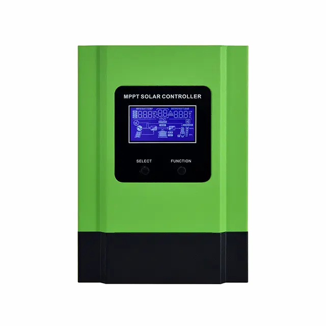
The Techfine MB series specification offers automatic sensing alongside listed battery-voltage platforms. This does not mean every controller automatically recognizes every platform advertised elsewhere in the range. Select the exact model and obtain its current manual before deciding whether automatic or fixed configuration is appropriate.
Keep voltage identification separate from chemistry
A voltage decision does not establish whether the connected battery is flooded lead-acid, gel, AGM or lithium. Batteries with similar nominal labels can require different voltage targets, temperature behavior and charging permissions. Selecting the correct platform while leaving an unsuitable default battery type can still produce the wrong charging behavior.
For an installation record, use three separate entries: nominal system voltage, battery chemistry and manufacturer-approved charge settings. Add the battery model, series arrangement and the source document that authorizes those values. A photograph showing only the controller’s voltage screen cannot prove the other entries are correct.
Why the startup sequence matters
The order of energizing equipment can determine which information is available when the controller initializes. Some controllers require the battery connection to be established before the PV side is enabled. Others have different permitted power arrangements. The sequence must come from the manual matching the supplied unit, rather than a procedure remembered from another installation.
Techfine’s linked controller manual describes identifying the connected battery at startup and checking the LCD indication against the actual system. Its filename mentions one current range while the document cover identifies another, so the cover model and delivered hardware must be reconciled before using the procedure. This document-control check is part of commissioning, not a reason to guess the intended instructions.
Connection and isolation work belongs to a qualified installer using the approved design. For the owner, the useful acceptance evidence is a recorded sequence reference, the initial displayed voltage and confirmation that configuration was completed before normal charging. This article is a verification framework rather than a live wiring sequence.
Prepare a voltage-identification worksheet
| Record | What it establishes | Evidence to retain |
|---|---|---|
| Battery arrangement | The intended nominal platform | Battery model and approved series/parallel drawing |
| Controller identity | Supported detection behavior | Full model suffix, firmware and matching manual |
| First displayed platform | The controller’s actual interpretation | Startup screen photograph with date |
| Battery profile | The charging program selected independently | Saved settings and battery instructions |
| Restart result | Behavior after an approved interruption | Qualified acceptance record and final display |
Treat an unexpected result as a stop point
If the detected platform differs from the design, do not raise charging targets until the display looks familiar. Record the result and have the installer establish the cause. The battery may be unusually discharged, a connection may be incomplete, or the controller may be operating from a saved fixed setting. These possibilities call for different corrections.
A lithium battery with an inactive output or an open BMS-controlled contactor can also change what is available at the controller. A missing voltage reading does not establish that the battery has no stored energy. Ask for the battery’s approved recovery and commissioning procedure, including any requirements for charger compatibility or external control.
Do not force a voltage selection simply to make a nonresponsive installation begin charging. First reconcile the measured condition, equipment identity and permitted operating range. Keep the original error or display photograph because it can help the supplier distinguish a setup issue from a product fault.
Understand what happens after a restart
Automatic detection behavior is not universal. One product may detect on first power-up and retain a setting; another may identify again after complete power loss. Victron’s referenced feature documentation gives an example of first-power-up detection with later manual configuration where required. That example demonstrates why restart assumptions cannot be transferred between brands or models.
For a site where battery protection can interrupt the controller supply, ask specifically what happens when power returns. Does the voltage setting persist? Is the battery profile retained? Does remote charging permission need to return separately? Answers should refer to the actual firmware and operating arrangement, not merely the word “automatic” in a brochure.
A practical acceptance example
Consider a hypothetical installation designed around a twenty-four-volt battery bank. The acceptance sheet identifies the bank arrangement and approved battery profile before startup. The installer follows the matching manual, records a twenty-four-volt system indication, confirms the saved charging settings and verifies normal behavior under an agreed operating condition. These are separate observations, even when made during the same visit.
If the equipment is later moved to a different battery platform, the previous acceptance sheet is no longer sufficient. The change requires compatibility review and a new configuration record. Retaining an old label or assuming that an automatic feature will correct every saved parameter creates an avoidable gap in the service history.
Make the setting understandable to the next technician
Place the commissioning record with the site’s equipment documentation, including the date and the person responsible for the accepted configuration. Distinguish factory defaults from settings deliberately selected for this battery. When a display offers both automatic and fixed choices, record which choice was actually saved rather than describing the controller only as capable of automatic operation.
This detail matters during replacement. A service technician may receive the same enclosure with a different revision or encounter a battery changed after the original installation. A clear record makes it possible to compare the current system with the accepted arrangement without relying on memory. Any later change should identify the reason, supporting manufacturer document and verification result, so the configuration history remains useful throughout the equipment’s service life.
Questions to resolve before handover
Does automatic sensing choose the battery type?
Do not assume it does. Confirm the chemistry and charge program independently, including any custom settings authorized by the battery manufacturer. A supported nominal voltage is only one part of compatibility.
Can a correct display replace measurement?
The display is evidence of the controller’s interpretation. Qualified electrical verification establishes whether the installed system matches the design. Keep both types of evidence where commissioning requirements call for them.
Should every restart be tested?
Define representative, manufacturer-approved recovery conditions with the installer. The objective is to document expected restoration behavior without repeatedly interrupting a charging system or creating unsupported test conditions.
Technical references: Techfine MB specifications; Techfine controller manual, model verification required; Victron automatic-detection example.