Parallel solar inverters can expand a system’s power capability, but expansion starts with compatibility rather than a cable purchase. Hardware versions, firmware, battery capacity, controls and the AC arrangement all need to form an approved system. Two inverters with similar names or equal kilowatt ratings are not automatically a compatible pair. Establish the supported architecture before ordering the first unit if expansion is part of the plan.
Define what expansion is supposed to achieve
Write down the initial demand and the expected future demand. Identify whether the aim is more single-phase power, a supported multi-phase arrangement, additional solar capacity or a resilience requirement. Those objectives are different. A product’s parallel capability does not establish every possible phase configuration, and adding another inverter does not automatically provide redundancy for the original installation.
Ask what must remain available if one unit stops. A shared battery, common control system or common AC connection can influence the answer. If continuity during service is important, make that a specific design requirement rather than inferring it from the number of cabinets. Compare the proposed failure behavior with the customer’s actual service needs.
Verify the exact supported model combination
Record complete model codes, DC voltage versions, AC output versions and hardware revisions. Request the manufacturer’s permitted combinations and maximum supported unit count. A series-level statement such as support for parallel operation is an invitation to check the configuration, not approval to mix every power rating in that family.
Victron’s VE.Bus parallel-system documentation illustrates how specific these rules can be: it identifies type and firmware matching requirements for its covered products. Those requirements are not a substitute for Techfine instructions. Obtain the applicable Techfine compatibility confirmation and use that as the project basis.
Separate built-in support from required accessories
Ask whether the quoted inverter has the necessary parallel hardware fitted, and which communication or current-sharing accessories are included. Confirm the correct accessory for the model and intended architecture. A connector that resembles a network socket is not evidence that a general-purpose network cable performs the required function.
List optional boards, approved cables and commissioning equipment separately in the quotation. Establish who supplies and configures them. This prevents an expansion project from reaching the site with two suitable cabinets but an incomplete control arrangement. Keep accessory part numbers with the system record so replacements can be identified accurately.
Treat firmware as part of the configuration
Ask the supplier which firmware versions are compatible and how version identification should be recorded. Units purchased months apart may not arrive with identical software. A planned expansion should include a review of the installed unit and the new supply, rather than assuming the newer unit can join without any preparation.
Firmware updates should follow the supplier’s approved process and a suitable service plan. Do not install an arbitrary package merely to make two version labels match. Preserve the existing configuration and identify any settings that require recommissioning. The aim is a supported system state, not simply the highest version number available.
Recalculate the battery requirement for the whole system
Additional inverter capacity increases potential demand on the DC source. Check the battery bank’s continuous and transient discharge capability, BMS limits and permitted operating conditions against the intended combined load. A large energy capacity in kilowatt-hours does not necessarily establish adequate discharge power. Both energy and power need to be reviewed.
Consider an illustrative expansion from a 2 kW operating load to a 4 kW operating load. If the added demand is actually used, the battery-side input power will also increase, with conversion losses included. The extra inverter does not create more stored energy. Runtime and battery capability therefore need a new assessment even when each inverter is individually compatible with the nominal DC voltage.
Review shared infrastructure and protection
The DC distribution, AC distribution, isolation and protective arrangements must be designed for the approved system. Existing infrastructure sized for one unit may not suit the expanded installation. Ask the designer to document what can remain and what must change. Do not treat an expansion as only a communications task.
Current sharing and voltage drop can depend on the physical installation. Follow the manufacturer’s requirements for the complete arrangement, including any symmetry or distribution requirements. Qualified personnel should design and install it. This article does not provide a connection sequence or permission to join live inverter outputs.
Keep PV allocation model-specific
Determine how the supported parallel system handles PV inputs. Do not assume that a string can be shared between inverter inputs or that total array power can be distributed arbitrarily. Each input retains its own voltage and current constraints, and the supported architecture must come from the matching manual.
Document each array group and the inverter receiving it. If future roof expansion is planned, reserve suitable physical space and assess the electrical arrangement now. A spare inverter position or unused connector does not prove that another string will be acceptable later. Recheck the design when the actual modules and layout are known.
Use a compatibility and handover worksheet
| Item | What to confirm | Record to keep |
|---|---|---|
| Inverter combination | Approved models, versions and unit count | Supplier confirmation and exact model codes |
| Control equipment | Required boards, cables and configuration | Accessory list and system diagram |
| Battery source | Combined power, energy and BMS capability | Battery limits and design assumptions |
| AC and PV arrangement | Supported topology and individual input limits | Approved electrical design |
| Commissioning | Load sharing, alarms and intended failure behavior | Qualified acceptance record |
Use the worksheet for both the initial installation and subsequent expansion. Identify unresolved questions before purchase. A supplier should be able to assess a clearly described system more effectively than a request asking only whether two devices “can work together.”
Start the Techfine discussion with the complete plan
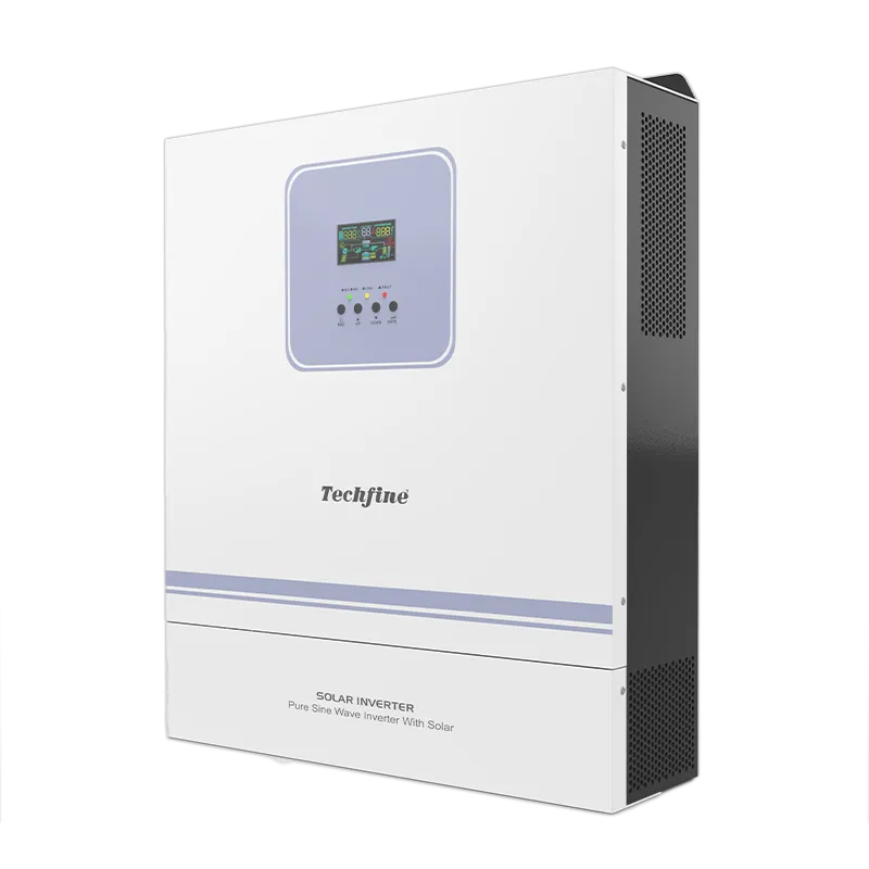
The Techfine GA Pro Plus specification identifies parallel capability for the series. Confirm the exact selected configuration, accessories and supported limits rather than treating the maximum advertised unit count as the correct project size. The Techfine product page can anchor the quotation discussion.
Send the initial and expansion load schedules, phase requirement, battery model, PV layout and proposed commissioning responsibilities. Ask whether later production revisions remain compatible and how that is checked at the time of expansion. Written confirmation reduces the chance that a future replacement or addition is selected only by appearance.
Frequently asked questions
Can different inverter brands be paralleled?
Do not assume that they can. Use only an explicitly supported architecture with documented compatibility. Similar AC voltage and power ratings are insufficient.
Does parallel operation double backup time?
No. Runtime depends on stored energy and the load. Additional conversion capacity does not increase battery energy.
Can one failed unit always be removed while the rest run?
That depends on the approved architecture and service procedure. Define the required behavior and obtain a model-specific answer before relying on it.