A solar backup inverter can have ample running power and stored energy yet still interrupt a sensitive load during a source change. Transfer time describes an important part of that event, but compatibility also depends on the connected equipment, operating mode and complete supply path. Specify what must keep working, then verify that requirement rather than assuming every appliance tolerates the same brief interruption.
Describe the consequence of an interruption
Start with the service affected. A lamp flicker, a router restart, a workstation shutdown and an interrupted industrial process have different consequences. Record whether the requirement is simply automatic power recovery or uninterrupted operation of a particular device. These are not equivalent outcomes, even if the device eventually turns itself back on.
Include the equipment around the obvious load. Keeping a desktop computer powered does not preserve a remote session if its router, network switch or external storage restarts. Map the complete service chain and identify the interruption tolerance of each component. This often reveals a smaller group that needs a more specific continuity solution than the rest of the building.
Read the transfer specification with its conditions
Determine which transition a published value describes: AC input to battery operation, recovery to AC input, a particular bypass transition or another operating change. Check whether it is typical or guaranteed under stated conditions. A number quoted without its transition and mode is incomplete information for a compatibility assessment.
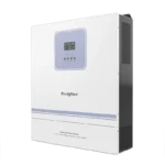
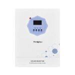
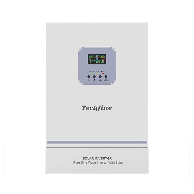
The Techfine GA Pro specification distinguishes transfer figures associated with different equipment modes. Use the matching model manual to confirm how the selected mode works. Do not take a number from a different product or assume the fastest listed mode applies automatically to every installation.
Distinguish transfer time from equipment hold-up
A load’s internal power supply may sustain operation for a short interval without normal input, depending on its design and operating condition. That capability belongs to the load, while transfer performance belongs to the supply arrangement. Compatibility requires both sides to be assessed together. A short transfer is not a universal promise that all connected devices will ride through.
Eaton’s APSINT3636VR specification explicitly advises checking load compatibility alongside its transfer-time statement. That is a useful procurement principle rather than a performance claim about Techfine. Obtain the actual load requirements and the proposed inverter’s documentation instead of relying on the general label “computer equipment.”
Include the complete power path
An installation can include external switching, protective equipment, intermediate distribution and additional backup devices. Determine which components participate in the transition and whether any delay lies outside the inverter’s own published value. The service experiences the complete arrangement, not only the most favorable component specification.
Also confirm that the load is actually connected to the supported backup output. A building can contain both backed-up and ordinary circuits. An inverter’s transfer capability cannot protect a device supplied from a circuit outside that arrangement. Keep the circuit schedule and system diagram with the load requirements.
Review voltage and frequency as well as duration
Loads can respond to supply changes beyond a complete loss of power. The accepted voltage range, frequency, waveform and behavior during recovery may matter to the application. Transfer-time comparison is therefore one part of a broader supply-quality review. Ask the equipment manufacturer which characteristics are relevant for the intended duty.
A motor controller, contactor or instrument can react differently from a modern electronic power supply. Do not generalize from a successful laptop demonstration to every device in a workshop. Where the consequence is significant, define acceptance with the relevant equipment supplier and a qualified system designer.
Build a continuity acceptance worksheet
| Load or service | Required behavior | Evidence needed |
|---|---|---|
| Network connection | No unwanted restart of the necessary devices | Complete network power chain and approved verification |
| Computer or storage system | Continued operation or controlled shutdown as specified | Equipment requirements and backup design |
| Process controls | Defined response to source changes | Control-system review and acceptance criteria |
| General lighting or convenience loads | Acceptable interruption and recovery | User requirement and supported circuit arrangement |
The worksheet should identify what constitutes a failure: a reboot, lost connection, dropped relay or data interruption, for example. Without that definition, an installer and customer can observe the same transition and disagree about whether the system passed. Clear criteria make the verification useful.
Verify under representative conditions
Agree on a commissioning plan that reflects the intended operating mode, normal background load and approved battery condition. Qualified personnel should use the manufacturer’s procedures and the site’s safety arrangements. This guide does not instruct a user to disconnect live grid wiring or force a battery into a protective shutdown.
Record the results at the service level as well as the inverter display. If the requirement is an uninterrupted network session, observing that the inverter changed modes is not enough. Check the relevant devices and application outcome. Preserve the equipment models and settings so the result has a clear scope.
Consider a dedicated continuity layer where needed
Some loads may need a separately selected UPS or another engineered continuity solution even when a solar inverter supplies the wider backup circuit. That additional layer must itself be compatible with the upstream supply and intended duty. Do not assume that placing two backup devices in series automatically solves every interruption problem.
Compare the architecture against the required service rather than buying a device solely because its advertised transfer number is smaller. Runtime, output quality, overload behavior, charging and recovery also matter. A well-defined small critical group can be easier to protect than an unnecessarily broad promise covering every circuit.
Prepare a Techfine application enquiry
Use the GA Pro series page to identify the proposed platform, then send the exact sensitive equipment models, circuit arrangement and required behavior. Ask for the applicable transfer specification and supported operating mode. Keep the answer tied to the quotation version.
If any device is replaced later, review its requirements before relying on the previous acceptance result. A new power supply or additional network component can change the continuity chain while the inverter remains unchanged. Documentation makes those changes easier to manage.
Frequently asked questions
Does a 10 ms or 20 ms figure guarantee no computer restart?
No. Match the exact supply behavior to the actual equipment and operating conditions. Verify the required service outcome.
Is automatic restart the same as uninterrupted operation?
No. A device can recover automatically after losing power while still interrupting its service, connection or process.
Does more battery capacity reduce transfer time?
Additional stored energy can affect runtime, but it does not by itself establish a different transfer specification. Review these requirements separately.