Battery management communication is a system function, not simply a cable between two familiar sockets. An inverter and lithium battery must agree on the electrical interface, message protocol and supported behavior. A display showing battery voltage does not prove that the inverter is receiving and obeying the BMS limits. Confirm compatibility for the exact equipment combination and verify the result during commissioning.
Separate electrical compatibility from communication compatibility
The battery’s voltage range, permitted power and charging requirements must suit the inverter before communications are considered. A data connection cannot make an unsuitable DC platform compatible. Start with the battery and inverter model codes, supported operating ranges and the approved installation arrangement. Then establish what management communication is required.
Some systems use a documented voltage-based operating arrangement, while others rely on information from a managed battery. Those are distinct configurations. Ask the suppliers which arrangement is supported for the proposed combination, including its limitations. Do not assume that selecting a menu option labelled lithium proves that full closed-loop communication is working.
Confirm the physical interface and cable specification
CAN and RS485 are examples of interfaces found in battery systems, but an interface name does not define every detail needed for interoperability. Connector pin assignments, cable requirements, supported ports and equipment configuration still matter. Two sockets with the same shape can serve different purposes or use different pin arrangements.
Request the approved cable or its manufacturer specification for the exact battery and inverter. Identify required accessories or communication modules in the quotation. Do not improvise a connection by trying ordinary network leads until one appears to work. Cable selection and installation should follow the equipment documentation under qualified supervision.
Confirm the protocol, not just the port
A protocol determines how the devices interpret messages. Two products can share an interface type without speaking the same supported protocol. Record the named protocol or compatibility mode, relevant firmware and any configuration required on both devices. A generic claim that a product supports BMS communication does not establish compatibility with every battery brand.
Victron’s battery compatibility resource illustrates a manufacturer approach built around documented battery integrations and system-specific information. It is not a list of batteries approved for Techfine. Obtain the corresponding confirmation from Techfine and the proposed battery supplier for the actual model pair.
Ask what information is exchanged and used
A useful compatibility discussion identifies the data and controls that affect operation. Depending on the supported system, relevant information may include state of charge, allowed charging and discharging limits, voltage targets, alarms or permission signals. Do not assume that every interface exposes all of these values or that every value shown on a screen controls the inverter.
Ask which device is authoritative for each limit and what the inverter does when a limit changes. This distinguishes a monitoring link from an active management arrangement. The acceptance criteria should describe the intended behavior, not merely require a communication icon to appear.
Build a compatibility record before purchase
| Item | What to establish | Evidence |
|---|---|---|
| Equipment identity | Exact inverter, battery and BMS versions | Model codes and supplier compatibility confirmation |
| Physical interface | Approved ports, cable and accessories | Matching manuals or approved accessory specification |
| Protocol configuration | Supported mode on both devices | Commissioning configuration record |
| Operating controls | Which limits and permissions are communicated | Documented behavior and acceptance results |
| Communication failure | Required alarm and supported response | Manufacturer-approved failure behavior |
Keep unresolved items visible. If one supplier says a combination is compatible while the other cannot confirm it, resolve that difference before installation. Identify who will support the complete arrangement, particularly if the battery is supplied separately from the inverter. A clear support boundary helps avoid competing explanations after commissioning.
Review communication-loss behavior
A reliable design needs a documented response when valid battery messages are no longer available. Ask whether charging or discharging is restricted, whether an alarm is raised, and how normal operation resumes. The correct behavior is model-specific; do not assume another installation’s fallback applies to this one.
Any verification of this behavior belongs in the manufacturer’s approved commissioning process. Do not disconnect arbitrary cables from an operating system or bypass BMS protections as an experiment. The objective is to confirm the supported response safely, with an agreed plan and qualified personnel.
Account for multiple battery modules
A battery bank containing several modules may present a coordinated system to the inverter through a defined architecture. Request the battery supplier’s instructions for supported module combinations and communication arrangement. More modules do not automatically mean the inverter should receive several independent connections.
Confirm how total capacity, available current and alarms are represented. A bank can have a physical capacity different from the value configured or reported to the inverter. Review the actual module count and the intended management configuration together, especially when expanding an existing bank or replacing one module.
Verify behavior rather than a single screen value
During commissioning, compare the device identities, expected battery information and relevant control status using the approved tools. Record which values are live and what they mean. State of charge may be useful to users, but a plausible percentage alone is not evidence that charging and discharging permissions are correctly integrated.
Keep the acceptance record tied to the installed firmware and settings. If a later update or battery replacement changes the integration, review the record again. Avoid treating the original compatibility statement as approval for unlimited future substitutions within either product family.
Discuss Techfine BMS support precisely
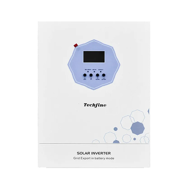
The Techfine QA series specification identifies built-in BMS communication for lithium batteries. Ask which battery models, protocol versions and accessories are supported for the exact inverter version. A series feature statement is a starting point for this discussion, not a universal interoperability guarantee.
Use the QA series product page to identify the platform in the enquiry. Send the battery and BMS datasheets, intended module count, charging requirements and required monitoring functions. Request a documented configuration and clear support responsibility from the suppliers.
Frequently asked questions
Does a working battery voltage display prove BMS communication?
No. The inverter can measure electrical voltage independently of a management data link. Verify the expected communication status and supported control behavior.
Can a cable solve every compatibility problem?
No. Cable correctness is only one condition. Protocol, firmware, equipment capabilities and configuration also need to align.
Should I disable the BMS if communication fails?
No. Preserve protective functions and follow the manufacturer’s support procedure. Any alternative operating configuration needs explicit approval for the complete system.